PT. ANT21 INDONESIA
PERUSAHAAN PENGOLAHAN AIR LIMBAH INDUSTRI
Water / Wastewater Treatment
Rukan Gading Bukit Indah Blok H No. 18
Kelapa Gading, Jakarta Utara 14240 Indonesia.
• Tel : 021 2245 9153
• Mobile : 0822 4625 5758 / 0813 9824 3323
Our Product
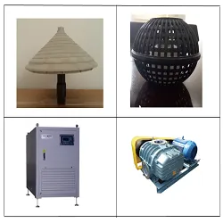
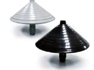 ① High Efficiency Diffuser
♧ Feature
• Highest possible fine bubble SOTE.
• Durable, impact-resistant.
• Non-clog, trouble-free efficient operation.
• Designed for resistance of compressed air heat in continuous operation.
• Easily adaptable to various types of existing basin.
• Reduce energy consumption with maximum transport efficiency
at low air flow rate High oxygen transfer rate
can be maintained continuously
• Operates during all seasons, even during severe conditions of plant
with high oxygen transfer rate.
• Low power consumption, durable.
• Triangulary arranged cone shape minimizes bubble coalescene
Bubbling occurs evenly over each cross-section
with a wide range of airflow.
♧ Application
• Wastewater treatment plant
• Sewage treatment plant
• Aeration tank,
• Livestock wastewater treatment plant
• Filtration plants
♧ Properties
• Size : D = 327mm
• Dispersive Formation : Cross-section / Entire circular body
• Material : ABS Copolymer , Nylon Connector : 20A (Socket)
• Air flow rates : 60~130L/min
♧ Customer
• PT. HYUNDAI INTI DEVELOPMENT / CIKARANG
• PT. SAMA INDAH / BANDUNG
• PT. MEWAH NIAGA JAYA / BANDUNG
• PT. SINAR PANGJAYA MULIA / BANDUNG
• PT. JERDYTEX / BANDUNG
• PT. ORIENTAL EMBROIDERY / BANDUNG
• PT. KEMARGA KURNIA TEXTILE INDUSTRY / BANDUNG
• PT. HARAPAN TEXTILE INDONESIA / BANDUNG
• PT. TAK INDONESIA
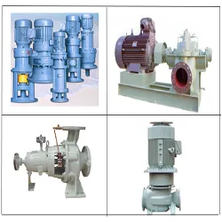
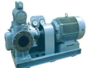 ⑤ Horizontal,
 External Gear Pump
with Built-in
Relief Valve
[200㎡/h ×~7kg/㎠]
♧ Usages and applications
01. Application
Lubrication oil, Fuel oil or other liquids with lubrication property.
02. Differential pressure
Up to 7kg/cm²
03. Bearing
Internally setted metal bearing, lubricated by the pumping liquid.
04. Shaft sealing
Gland packing or mechanical seal.
05. Relief valve
Built-in type, Setting pressure
: minimum 2.2kg/cm² maximum 7.2kg/cm²
06. Pumping temperature
Up to 70°C
07. Flanges
KS or JIS 10kg/cm², rating. FF.
08. Standard capacity
Calculated at 25.8cst. (Rw.No.1, 100sec.)
Rpm-slip of motor considered
* The out of the above range can be supplied
according to customer’s order placement
♧ Operating data
Capacity : 40m³/Hr ~ 200m³/Hr
Head : 3Kg/㎠ ~ 7Kg/㎠
Suction Bore : Ø150mm ~ Ø250mm
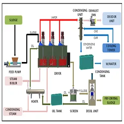
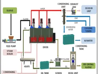 ② Sludge Dryer
 (Sludge Fry-Drying System)
♧ Fry-Drying System ?
■ Process description
1. Sludge Storage Tank & feeding system.
- Sludge in the store tank is transferred to the reactor
with a pump or screw conveyor.
2. Reactor ( dryer).
- The sludge charged into the reactor is dispersed in the hot
oil by a high speed agitator (Temp: 130-150C).
-The moisture in the sludge is evaporated by the hot oil and
the moisture is turns into steam.
-The sludge whose moisture has been removed is discharge
to the outside by the conveyor.
3. Screen system.
- Fried sludge in the oil is seperated by oil and sludge in
the vibrator screen.
4. Pressing Unit.
-After screening, remove any remaining oil from sludge by pressing.
5. Condensing unit.
-when the moisture in the sludge becomes vapor and exits
to the outside, it is condensed by the heat exchanger.
6. Deodor Unit
- A trace amount of gas that can nit be condensed is
removed from the odor preventation facility.
7. Condensing Tank.
- The condensate removed from the heat excharger is sent
to the existing waste water treatment plant.
8. Oil Circulation Tank.
- After passing the screen, the oil is brought back into the reactor.
What's New
Kelapa Gading, Jakarta Utara 14240 Indonesia.


